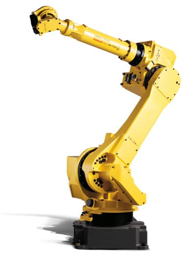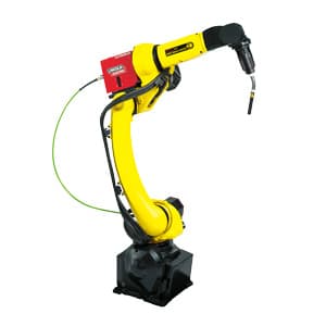
10 more high-priority FANUC alarm codes — SRVO-230 safety chain, SRVO-024 move error excess, SRVO-045 HCAL, SRVO-067 OHAL2. Zero overlap with Part 1.
Part 1 of this series covered the ten alarms most likely to stop your production. This Part 2 continues with ten more — sourced from the most-searched FANUC fault codes across maintenance forums, technician communities, and robot integrator support logs worldwide. Each alarm has a distinct cause and fix path. Keep both parts on the shop floor.
Before attempting any fix: press MENU → ALARM → F3 (HIST) to view the full alarm history. Alarms fire in chains — identify and fix the first alarm in the list, not the last one displayed. Press F1 (ACTIVE) to return to the active alarm screen.
1. SRVO-230 / SRVO-231: Safety Chain Fault
SRVO-230 and SRVO-231 are the most searched FANUC robot alarms online — and for good reason. They indicate a timing violation in the dual-channel emergency stop safety circuit. The R-30iB controller uses two independent E-stop channels (Chain 1 = +24V leg, Chain 2 = 0V leg) that must open and close within a precise time window. When one channel transitions too slowly — due to worn contacts, a damaged TP cable, or a failing switch — the controller flags the mismatch and locks out. SRVO-230 = Chain 1 fault; SRVO-231 = Chain 2 fault.
Root causes and fix steps:
- Worn deadman switch contacts — the most common hardware cause. The deadman has two independent channels; degraded contacts cause a timing mismatch. Replace both switches as a matched pair.
- Damaged TP cable — a kinked or pinched cable at the strain relief can intermittently break one channel. Inspect where it exits the pendant housing and at the controller inlet.
- Faulty E-stop button — test by substituting a known-good pendant. If the alarm disappears with the replacement, the original button or cable is the cause.
- Failed safety relay — relay contact switching time may be out of spec. Measure against the safety relay datasheet.
- Reset procedure: press and release the TP E-stop → MENU → ALARM → HIST → F4 [RES_1CH] for SRVO-230, or F5 [RES_2CH] for SRVO-231. If reset fails, navigate to SYSTEM → ESTOP CONFIG.
- CRITICAL: never bypass or ignore this alarm. A degraded channel means partial E-stop coverage only. Fix before returning to production.
2. SRVO-024: Move Error Excess
SRVO-024 fires when the servo tracking error exceeds the threshold in $PARAM_GROUP.$MOVER_OFFST during motion — the robot cannot follow the commanded trajectory. This is distinct from SRVO-023 (Stop error excess), which fires when the robot is stationary and cannot hold position. SRVO-024 is a motion-tracking failure; SRVO-023 is a holding failure.
Causes and fix sequence:
- Physical obstruction — inspect the robot arm, tool, and fixtures for any interference that was not there before.
- Wrong payload declaration — if payload is set too low, the servo loop does not allocate enough torque and falls behind. Check MENU → SETUP → Frames → PAYLOAD.
- Worn joint bearings or insufficient grease — mechanical friction the servo cannot overcome at the commanded speed. Listen for unusual sounds on the offending joint.
- Incoming power supply drop — low AC voltage starves the servo amplifier. Measure incoming voltage at the cabinet input under load.
- Motor power cable — a loose pin or partial break causes intermittent current loss. Inspect cable and connectors at the motor and amplifier.
- Temporary diagnostic: reduce the speed on the offending motion line. If the alarm disappears at lower speed, the root cause is mechanical or electrical — not a servo gain setting.
3. SRVO-075: Pulse Not Established
SRVO-075 is the classic Monday-morning alarm — the robot sat powered off over the weekend, encoder batteries died, or batteries were swapped with the controller off, and the absolute pulsecoder has lost its position reference. The encoder's zero position is gone; the robot refuses to move until you re-establish the pulse count by jogging the affected axis through at least one complete motor revolution. This is not a hardware failure — it is a recoverable condition that takes about two minutes per axis.
Resolution steps:
- Press RESET. The alarm clears only if battery power is now stable — confirm with MENU → SYSTEM → Config → Battery voltage.
- Enable T1 mode and press the deadman switch.
- Jog the affected axis continuously in one direction through at least one complete motor revolution — approximately 20–45 degrees of arm movement depending on gear ratio.
- Verify: MENU → SYSTEM → Master/Cal → Pulse Match. The Pulse Count field must show a real number, not asterisks (****). If asterisks remain, jog further.
- If multiple axes show SRVO-075, jog each in sequence.
- After re-establishing all pulses, verify mastering data is intact: MENU → SYSTEM → Master/Cal → confirm all axes show "DONE." If mastering data was lost, perform Quick Mastering or Zero-Degree Mastering.
4. SRVO-045 HCAL: Instantaneous Overcurrent
SRVO-045 HCAL (High Current ALarm) fires when the servo amplifier detects an instantaneous current spike exceeding its protection threshold on the motor power circuit. This is a hard shutdown to prevent amplifier damage. The key diagnostic question: is the fault in the motor or cable, or in the amplifier itself? The answer determines whether you replace a cable or an entire servo amplifier module.
Hardware diagnostic tree:
- Step 1 — Isolate: disconnect the motor power cable (U, V, W leads) from the servo amplifier output terminals. Do not power off the controller — only disconnect the motor cable.
- Step 2 — Enable: restore power and try to enable servos (SHIFT + DEADMAN + FWD in T1). If SRVO-045 does not fire, the fault is in the motor or cable. Proceed to insulation test.
- Step 3 — If the alarm fires immediately with the cable disconnected, the fault is in the amplifier. Replace the servo amplifier module.
- Insulation test: with motor cable disconnected, use a megohmmeter at 500V DC to measure insulation from each phase (U, V, W) to PE (ground). Normal: above 1 MΩ. Below 100 kΩ indicates motor winding failure — replace the motor.
- Cable test: if insulation is good, check the motor power cable for intermittent shorts. Also inspect fiber optic signal cable connections at both ends.
5. SRVO-067 OHAL2: Pulsecoder Overtemperature
SRVO-067 OHAL2 fires when the encoder (pulsecoder) internal thermostat trips above approximately 90–95°C. The encoder is mounted directly on the motor, so overtemperature usually means the motor itself is running too hot. The controller will not reset the alarm until the encoder physically cools below the reset threshold — there is no shortcut.
Causes and fix:
- Allow to cool fully — do not attempt to reset immediately. The thermostat has hysteresis and must drop well below 95°C before the reset will succeed. Allow at least 20–30 minutes.
- After cooling, perform a cold start (power off → wait 30 seconds → power on) to fully clear the alarm.
- Check motor cooling fans — on larger robots (J1, J2, J3 axes), servo motors have integral cooling fans. A failed fan causes progressive overheating during a production run. Listen for fan operation.
- Check ambient temperature — in Israeli summer conditions, robot enclosures can reach 45–50°C. Verify cabinet fan and filters are clean. Add forced ventilation if needed.
- Reduce cycle speed or add dwell — if the alarm appears only at high cycle rates, the motor is thermally overloaded. Reduce speed or add a pause between cycles.
- Check for mechanical binding — a joint running hotter than others at the same speed indicates mechanical resistance. Check grease condition and bearing health on that axis.
6. SRVO-080 OVC: Sustained Overcurrent
SRVO-080 OVC (OverCurrent) fires when the servo amplifier RMS current exceeds its rated limit over a sustained period — unlike SRVO-045 HCAL, which is an instantaneous spike. OVC means the motor is consistently working too hard. The most common cause: the payload declaration is wrong. The servo loop uses the declared payload to calculate expected motor current; if it is too low, the motor draws more than the servo anticipated on every move.
Causes and fix:
- Wrong payload declaration — verify tool weight and center-of-gravity at MENU → SETUP → Frames → PAYLOAD. Even a 1–2 kg error on a borderline payload can cause OVC. Re-run the payload estimation utility if available.
- Insufficient joint lubrication — check grease condition on the affected axis. FANUC recommends grease replacement every 3,500–5,000 hours depending on model. A stiff joint draws significantly more current than a well-lubricated one.
- Excessive tool inertia — if tooling was recently changed and the alarm appeared afterward, the new tool may have higher moment of inertia than declared. Update payload inertia settings.
- Amplifier running hot — OVC threshold effectively drops as amplifier temperature rises. Check cabinet ventilation and clean amplifier air filters.
- Pattern diagnosis: if OVC fires at a specific joint angle every cycle, the cause is likely mechanical at that configuration. Check for binding or insufficient grease at that arm position.
7. SRVO-012: Power Fail Recovery
SRVO-012 fires after the controller detects and recovers from a power interruption — a voltage dip, complete outage, or accidental disconnect. It is not a hardware fault; it is a notification that power was lost and restored. The concern is the robot's state during the power event: did it stop mid-move? Is mastering data intact? Are all I/O states safe to resume from?
Safe recovery protocol:
- Press RESET on the teach pendant. The robot will enable if no other faults are present.
- Check alarm history (MENU → ALARM → HIST) to see what alarms fired before and during the power event — these reveal the robot's state at the moment of power loss.
- Verify mastering data: MENU → SYSTEM → Master/Cal → confirm all axes show "DONE" status. Power events rarely corrupt mastering, but always confirm before resuming production.
- Inspect the physical robot position — if the arm stopped mid-move, manually jog to a safe home position before resuming AUTO mode.
- Check all I/O states before resuming: conveyors, grippers, fixtures, and safety gates must all be in known states before sending the first AUTO cycle.
- If SRVO-012 fires repeatedly without actual power events, investigate incoming power stability — a failing UPS, voltage sags on the plant supply, or a loose cabinet connection can cause phantom power-fail events.
8. SRVO-043 DCAL: Per-Axis Regenerative Discharge
SRVO-043 is a per-axis variant of the DCAL family. Where SRVO-023 indicates a general discharge problem in the servo system, SRVO-043 fires on a specific axis and includes the axis identifier in the alarm message (for example: G:1 A:2 = group 1, axis 2, typically J2). This tells you exactly which amplifier module is involved, making the diagnosis faster and more targeted.
Root causes and fixes:
- Identify the axis from the alarm message (G:n A:m) — that axis's amplifier module is the starting point. Check which physical joint corresponds to that axis number.
- Too-fast deceleration on that axis — reduce speed, add FINE termination (extends deceleration distance), or reduce CNT values on motions that heavily use that joint.
- Regen resistor for that amplifier module — measure resistance and replace if out of spec. Some multi-axis amplifier units share one regen resistor; a failed resistor affects only the axes on that module.
- Excessive payload inertia at that joint — a high-inertia tool stores more kinetic energy during deceleration. Verify declared payload inertia matches the actual tool.
- If SRVO-043 fires on multiple axes simultaneously, the issue is likely a common power event — check incoming AC voltage and DC bus capacitor condition.
9. SRVO-105: Controller Door / E-Stop Detection
SRVO-105 fires when the controller cabinet door interlock opens, when the E-stop circuit shows an anomaly that does not fit the known E-stop categories (SRVO-001, -002, -007), or when emergency stop line wiring has a fault the software cannot specifically classify. It is a catch-all for E-stop hardware anomalies at the cabinet level.
Resolution steps:
- Close the controller cabinet door firmly and press RESET — many SRVO-105 incidents are simply doors left ajar after maintenance.
- If reset fails, check E-stop line wiring using the general connection diagram for your controller (R-30iB or R-30iB Plus) — inspect EAS1/EAS2 and EES1/EES2 terminals.
- Inspect the door interlock switch — a small reed or microswitch on the cabinet door frame. Measure contact continuity with the door closed. Open contact with door closed = faulty switch.
- Check safety relay inputs at the controller backplane — degraded relay contacts can generate transient E-stop signals that trigger SRVO-105.
- After any wiring repair: cycle power and confirm the alarm does not recur before re-enabling the robot.
10. SRVO-044 HVAL: DC Bus High Voltage
SRVO-044 HVAL (High Voltage ALarm) fires when the DC bus voltage in the servo amplifier main circuit rises above the safe operating limit. This is the opposite direction from SRVO-043 DCAL — DCAL is about regenerative energy that cannot discharge; HVAL is about too much voltage arriving from the AC supply, or from regenerative energy causing the bus to rise faster than it can dissipate. The most common cause is incoming AC voltage above specification.
Causes and fix:
- Measure incoming 3-phase AC voltage at the cabinet input. On 200V systems, normal range is 200–230V (alarm threshold: approximately 253V). On 400V systems, normal range is 380–480V (alarm threshold: approximately 530V).
- If voltage is high, contact the facility electrician — the issue is upstream in plant power distribution, not in the robot.
- Rapid deceleration on high-inertia moves can cause transient HVAL: when the motor regenerates faster than the DC bus can dissipate, voltage climbs. Reduce deceleration rates and check regen resistor condition.
- If incoming voltage is within spec and the alarm is persistent, the amplifier's overvoltage detection circuit may have failed. Replace the servo amplifier.
- Check power factor correction and supply regulation if HVAL correlates with other equipment switching on or off in the facility.
If you are dealing with a recurring alarm that you cannot resolve, Xpert Robotics offers remote and on-site diagnostics for FANUC systems throughout Israel — with emergency response within 8 hours.